Universal Aluminium Enclosure for RF Circuits
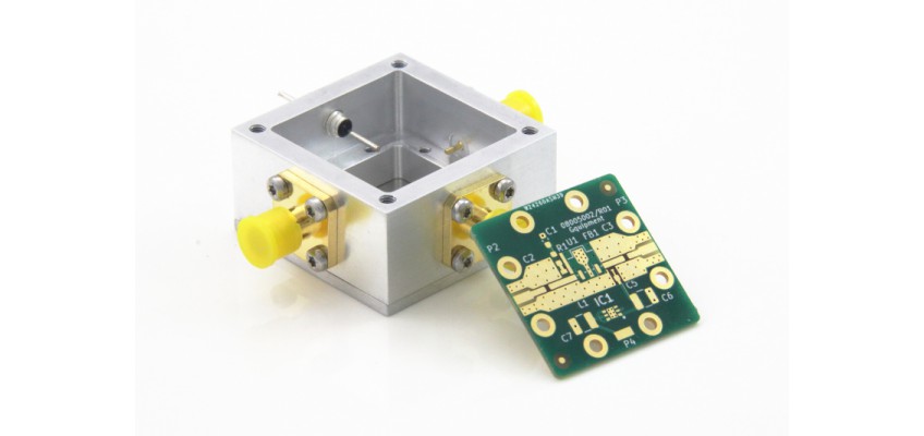
Every RF engineer faces the challenge of getting the PCB into an enclosure without sacrificing RF performance. An enclosure that allows you to easily swap PCBs not only makes life easier, but also speeds up the prototyping process. That, in a nutshell, is what the RF-Enclosure-MINI is designed for.
It can be used as:
- A test fixture to test RF components that do not have a coaxial connector. The most obvious example is measuring an SMD component.
- An enclosure to support the development process of an RF circuit such as a mixer, a power splitter, a coupler, an LNA, a Bias-T, etc. A revision of the PCB can easily be exchanged for a new one because the SMA connectors are removable.
- For small batch production. The RF-ENCL-MINI is a flexible and turnkey solution for a typical RF module. You save design and production time for the housing.
The enclosure is made from a CNC-machined aluminum solid. Tolerances are smaller than 0.1 mm. The aluminum is nickel-plated, which makes it a durable product.
1. Features of the RF-Eclosure-MINI
The RF-ENCL-MINI is a housing with many functions. They are all listed in this section.
Approx 1 inch2 of real estate.
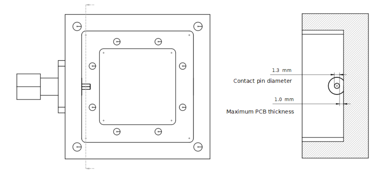
The dimensions of the enclosure were chosen in order to support a PCB size of 26.6 mm x 26.6 mm. This matches well with typical, relatively small-sized RF module applications. While it offers enough real estate for those designs that use more components.
The bottom of the PCB can also be partly populated because the bottom of the PCB hangs 0.6 mm above the bottom plate of the housing.
PCB mounting
The PCBs are mounted at the aluminium body of the enclosure and can be fastened with up to 8 screws. This way, a good low resistance path from PCB to enclosure and SMA ports is guaranteed.
The housing supports PCB substrate heights between 0.7 and 1.0 mm. There is a trade-off between RF performance and PCB substrate height because the SMA connector pin has a fixed position. The best performance is achieved at a substrate height of 1.0 mm. There is an application note that lists various options with their impact on performance. Along with reference designs in GitHub.
Easy interchange of PCB's
The enclosure uses a bottom- and top- cover that is attached to the enclosure body with screws. Making it easy to open. The SMA connectors can be removed too. This makes PCB interchanges very straight forward. The enclosure is therefore very handy in the prototyping phase of your project and / or as a testbed for PCBs.
SMA ports
The enclosure uses straight, flanged SMA connectors that fit exactly into the enclosures hole, with its teflon isolator traveling through the aluminium enclosure wall. This way, the coaxial configuration is maintained up to the terminating connector pin. Which lands on the PCB directly. This design keeps VSWR at a minimum. There are two SMA connector types that can be used:
- an SMA 18 GHz connector, brass body, gold plated. This is the default option.
- an SMA 18 GHz stainless steel connector which should be used in harsher environments and /or when many mating cycles are expected.
The RF-ENCL-MINI has three SMA ports. Unused ports can be closed with a special cover plate.
DC power port
The enclosure is equipped with a ground terminal, and a feedthrough capacitor for applying power. When not in use, the holes can be covered or filled up with dummy screws.
Low thermal resistance
The body of the enclosure is solid milled aluminium. This eliminates joints and is a great heat conductor too. Which can be beneficial when heat generated by your design must be transferred to the enclosure's surrounding.
2. Assembly
We made a video that shows how to assemble a RF-ENCL-MINI. It also gives a good look and feel of the enclosure.
3. Two Versions
The MINI enclosure comes in two flavours:
- The RF-ENCL-MINI-YF-01, enclosure with mounting flange
- The RF-ENCL-MINI-NF-01,without a mounting flange
References
- Datasheet: RF-ENCL-MINI-R01-XX
- Application note : application note
- Reference designs: reference designs