» Do not allow new products at this time.
Power splitter / combiners from DC up to 6 GHz
Subcategories
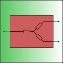
Power splitters using a three-resistor configuration vectorially add or split power signals. Because resistors are frequency-independent, these splitters are very broadband in nature, starting from DC and going well into the GHz range. The drawback of these splitters is that because of their resistive characteristics they add 3 dB of power loss to the power reduction of 3 dB caused by the power splitting itself.
Resistive power splitters are best used where power loss is not critical or where truly broad bandwidth is mandatory. They are typically found in the lab.
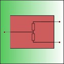
Please notice that there are also power splitters using a two-resistor configuration. They work differently and are designed for only two specific applications.
Resistive power splitters that use a two-resistor configuration (2R) should be used only for applications where the output power values are mathematically divided or for power-leveling applications in which the splitter is part of a feedback loop. For all other applications, use a 3R power splitter.
What makes a 2R splitter unique is the fact that the power is always equal at both output terminals. Therefore, any power reflected at one port will also be emanated at the other output port. This makes this kind of splitter the only correct choice for the above-mentioned applications.
An example of an application in which the output values are mathematically divided is a setup where one output of the splitter is used as a reference value A and the other port feeds some DUT which in response outputs a signal B. Then, the A and B signals are measured with an analyzer that computes the gain of the DUT by dividing B by A.
In power-leveling applications, a feedback process is used to set the power of one output port (A). Because any reflection at the other output port (B) will also emanate at the first port (A), this will be compensated for automatically (because port A is part of the closed feedback loop). In this manner, port (B) has an effective transmission coefficient of nearly 0.
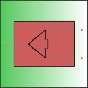
The Wilkinson power splitter, also called a magic tee (MT), is designed to not waste power—an important feature when power loss is not acceptable. Also, the high isolation between the two splitting ports can be an important property of this type of splitter. For example, it can prevent oscillator pulling when combining two signals that are close in frequency.
This type of power splitter uses a resistor bridge in combination with an RF transformer to create a power splitter. Due to its resistive design, 3 dB of power is wasted in addition to the 3 dB of power reduction resulting from the power-splitting action. The use of the RF transformer will define its usable frequency range.
The strongest aspect of this design is the very high isolation between the splitting ports, which can easily go into the region of 30 dB and much higher! This feature makes this splitter a very capable directional coupler. The HY1 series can therefore be used as splitters or directional couplers, which makes them versatile devices.
Wilkinson splitter based design
Based on a resistive bridge design; excellent performance at the lower end of the spectrum.
This module features two mounting flanges.
Wilkinson splitter based design
Based on a resistive bridge design; excellent performance at the lower end of the spectrum.
Wilkinson splitter based design
Based on a resistive bridge design; excellent performance at the HF, VHF and well into the UHF band.
Wilkinson splitter based design
Based on a resistive bridge design; excellent performance at the HF, VHF and well into the UHF band.
This module...